In internal combustion engines, variable valve timing (VVT) is the process of altering the timing of a valve lift event, and is often used to improve performance, fuel economy or emissions. It is increasingly being used in combination with variable valve lift systems. There are many ways in which this can be achieved, ranging from mechanical devices to electro-hydraulic and camless systems. Increasingly strict emissions regulations are causing many automotive manufacturers to use VVT systems. In this article, you will learn about the most common things of VVT with Pritish Kumar Halder.
Two-stroke engines use a power valve system to get similar results to VVT.

Basic Theory
After multi-valve technology became standard in engine design, Variable Valve Timing becomes the next step to enhance engine output, no matter power or torque.
As you know, valves activate the breathing of engine. The timing of breathing, that is, the timing of air intake and exhaust, is controlled by the shape and phase angle of cams. To optimise the breathing, engine requires different valve timing at different speed. When the rev increases, the duration of intake and exhaust stroke decreases so that fresh air becomes not fast enough to enter the combustion chamber, while the exhaust becomes not fast enough to leave the combustion chamber. Therefore, the best solution is to open the inlet valves earlier and close the exhaust valves later. In other words, the Overlapping between intake period and exhaust period should be increased as rev increases.
 Without Variable Valve Timing technology, engineers used to choose the best compromise timing. For example, a van may adopt less overlapping for the benefits of low speed output. A racing engine may adopt considerable overlapping for high speed power. An ordinary sedan may adopt valve timing optimise for mid-rev so that both the low speed drivability and high speed output will not be sacrificed too much. No matter which one, the result is just optimised for a particular speed.
With Variable Valve Timing, power and torque can be optimised across a wide rpm band. The most noticeable results are:
-
- The engine can rev higher, thus raises peak power. For example, Nissan’s 2-litre Neo VVL engine output 25% more peak power than its non-VVT version.
- Low-speed torque increases, thus improves drivability. For example, Fiat Barchetta’s 1.8 VVT engine provides 90% peak torque between 2,000 and 6,000 rpm.
Variable Lift
In some designs, valve lift can also be varied according to engine speed. At high speed, higher lift quickens air intake and exhaust, thus further optimise the breathing. Of course, at lower speed such lift will generate counter effects like deteriorating the mixing process of fuel and air, thus decrease output or even leads to misfire. Therefore the lift should be variable according to engine speed.
1) Cam-Changing VVT
Honda pioneered road car-used VVT in the late 80s by launching its famous VTEC system (Valve Timing Electronic Control). First appeared in Civic, CRX and NS-X, then became standard in most models.
You can see it as 2 sets of cams having different shapes to enable different timing and lift. One set operates during normal speed, say, below 4,500 rpm. Another substitutes at higher speed. Obviously, such layout does not allow continuous change of timing, therefore the engine performs modestly below 4,500 rpm but above that it will suddenly transform into a wild animal.
This system does improve peak power – it can raise red line to nearly 8,000 rpm (even 9,000 rpm in S2000), just like an engine with racing camshafts, and increase top end power by as much as 30 hp for a 1.6-litre engine !! However, to exploit such power gain, you need to keep the engine boiling at above the threshold rpm, therefore frequent gear change is required. As low-speed torque gains too little (remember, the cams of a normal engine usually serves across 0-6,000 rpm, while the “slow cams” of VTEC engine still need to serve across 0-4,500 rpm), drivability won’t be too impressive. In short, cam-changing system is best suited to sports cars.
Honda has already improved its 2-stage VTEC into 3 stages for some models. Of course, the more stage it has, the more refined it becomes. It still offers less broad spread of torque as other continuously variable systems. However, cam-changing system remains to be the most powerful VVT, since no other system can vary the Lift of valve as it does.
Example – Honda’s 3-stage VTEC
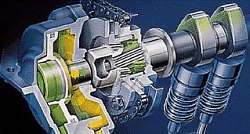
Honda’s latest 3-stage VTEC has been applied in Civic sohc engine in Japan. The mechanism has 3 cams with different timing and lift profile. Note that their dimensions are also different – the middle cam (fast timing, high lift), as shown in the above diagram, is the largest; the right hand side cam (slow timing, medium lift) is medium sized ; the left hand side cam (slow timing, low lift) is the smallest.
This mechanism operate like this :
Stage 1 ( low speed ) : the 3 pieces of rocker arms moves independently. Therefore the left rocker arm, which actuates the left inlet valve, is driven by the low-lift left cam. The right rocker arm, which actuates the right inlet valve, is driven by the medium-lift right cam. Both cams’ timing is relatively slow compare with the middle cam, which actuates no valve now.
Stage 2 ( medium speed ) : hydraulic pressure (painted orange in the picture) connects the left and right rocker arms together, leaving the middle rocker arm and cam to run on their own. Since the right cam is larger than the left cam, those connected rocker arms are actually driven by the right cam. As a result, both inlet valves obtain slow timing but medium lift.
Stage 3 ( high speed ) : hydraulic pressure connects all 3 rocker arms together. Since the middle cam is the largest, both inlet valves are actually driven by that fast cam. Therefore, fast timing and high lift are obtained in both valves.
2) Cam-Phasing VVT
Cam-phasing VVT is the simplest, cheapest and most commonly used mechanism at this moment. However, its performance gain is also the least, very fair indeed.
Basically, it varies the valve timing by shifting the phase angle of camshafts. For example, at high speed, the inlet camshaft will be rotated in advance by 30° so to enable earlier intake. This movement is controlled by engine management system according to need, and actuated by hydraulic valve gears.
 Note that cam-phasing VVT cannot vary the duration of valve opening. It just allows earlier or later valve opening. Earlier open results in earlier close, of course. It also cannot vary the valve lift, unlike cam-changing VVT. However, cam-phasing VVT is the simplest and cheapest form of VVT because each camshaft needs only one hydraulic phasing actuator, unlike other systems that employ individual mechanism for every cylinder.
Continuous or Discrete
Simpler cam-phasing VVT has just 2 or 3 fixed shift angle settings to choose from, such as either 0° or 30°. Better system has continuous variable shifting, say, any arbitary value between 0° and 30°, depends on rpm. Obviously this provide the most suitable valve timing at any speed, thus greatly enhance engine flexiblility. Moreover, the transition is so smooth that hardly noticeable.
Intake and Exhaust
Some design, such as BMW’s Double Vanos system, has cam-phasing VVT at both intake and exhaust camshafts, this enable more overlapping, hence higher efficiency. This explain why BMW M3 3.2 (100hp/litre) is more efficient than its predecessor, M3 3.0 (95hp/litre) whose VVT is bounded at the inlet valves.
In the E46 3-series, the Double Vanos shift the intake camshaft within a maximum range of 40° .The exhaust camshaft is 25°.
3)Cam-Changing + Cam-Phasing VVT
Combining cam-changing VVT and cam-phasing VVT could satisfy the requirement of both top-end power and flexibility throughout the whole rev range, but it is inevitably more complex. At the time of writing, only Toyota and Porsche have such designs. However, I believe in the future more and more sports cars will adopt this kind of VVT.
Example: Toyota VTL-i
- Continuous cam-phasing variable valve timing
- 2-stage variable valve lift plus valve-opening duration
- Applied to both intake and exhaust valves
The system could be seen as a combination of the existing VVT-i and Honda’s VTEC, although the mechanism for the variable lift is different from Honda.
Like VVT-i, the variable valve timing is implemented by shifting the phase angle of the whole camshaft forward or reverse by means of a hydraulic actuator attached to the end of the camshaft. The timing is calculated by the engine management system with engine speed, acceleration, going up hill or down hill etc. taking into consideration. Moreover, the variation is continuous across a wide range of up to 60°, therefore the variable timing alone is perhaps the most perfect design up to now.
What makes the VVTL-i superior to the ordinary VVT-i is the “L”, which stands for Lift (valve lift) as everybody knows. Let’s see the following illustration
Like VTEC, Toyota’s system uses a single rocker arm follower to actuate both intake valves (or exhaust valves). It also has 2 cam lobes acting on that rocker arm follower, the lobes have different profile – one with longer valve-opening duration profile (for high speed), another with shorter valve-opening duration profile (for low speed). At low speed, the slow cam actuates the rocker arm follower via a roller bearing (to reduce friction). The high speed cam does not have any effect to the rocker follower because there is sufficient spacing underneath its hydraulic tappet.
VVT’s benefit to fuel consumption and emission
EGR (Exhaust gas recirculation) is a commonly adopted technique to reduce emission and improve fuel efficiency. However, it is VVT that really exploit the full potential of EGR.
In theory, maximum overlap is needed between intake valves and exhaust valves’ opening whenever the engine is running at high speed. However, when the car is running at medium speed in highway, in other words, the engine is running at light load, maximum overlapping may be useful as a mean to reduce fuel consumption and emission.
Since the exhaust valves do not close until the intake valves have been open for a while, some of the exhaust gases are recirculated back into the cylinder at the same time as the new fuel / air mix is injected. As part of the fuel / air mix is replaced by exhaust gases, less fuel is needed. Because the exhaust gas comprise of mostly non-combustible gas, such as CO2, the engine runs properly at the leaner fuel / air mixture without failing to combust.
Reference
https://www.austincc.edu/wkibbe/vvt.htm


