Vacuum ejectors, or simply ejectors, are a type of vacuum pump that produces vacuum by means of the venturi effect. However, unlike mechanical vacuum pumps, vacuum ejectors do not contain any moving parts; they use a working fluid (usually a gas that is made to flow through a jet nozzle) as a source of power to move a secondary fluid.
This article covers the basic working principle of vacuum ejectors, particularly the simple, single-stage type. It will also provide some key design calculations that engineers should know about these vacuum-providing devices.
Water aspirator
The cheap and simple water aspirator is commonly used in chemistry and biology laboratories and consists of a tee fitting attached to a tap and has a hose barb at one side. The flow of water passes through the straight portion of the tee, which has a restriction at the intersection, where the hose barb is attached. The vacuum hose should be connected to this barb. In the past, water aspirators were common for low-strength vacuums in chemistry benchwork.
However, they are water-intensive, and depending on what the vacuum is being used for (e.g. solvent removal), they can violate environmental protection laws such as the RCRA by mixing potentially hazardous chemicals into the water stream, then flushing them down a drain that often leads directly to the municipal sewer.
Their use has decreased somewhat as small electric vacuum pumps are far more effective, environmentally safe, and have become more affordable, but the unmatched simplicity and reliability of this device have caused it to remain popular for small labs or as a backup.
Another, much larger version of this device is used in maritime operations as a device to dewater (drain) areas in a ship that have been flooded in emergency situations. Typically referred to as an eductor in these applications, this is preferred over electrical pumps due to their simplicity, compact size, and greatly mitigated risk of explosion in the event that flammable liquids and/or vapors are present.
Additionally, unlike many mechanical pumps, they can also pass debris as the eductor has no moving parts that can be fouled. This makes an eductor especially useful in situations where fitting a debris strainer to the suction port will present more issues than it resolves. The size of the debris that can be passed depends on the physical size of the eductor.
Sizes, flow ratings, and applications vary, including eductors that are permanently installed (typically used in very large spaces, such as a ship’s main engine room), or portable models that can be lowered into spaces by a rope and supplied and drained through firefighting hoses. Most are supplied through a ship’s firefighting main, and portable models can also be supplied by an emergency pump, provided it can supply sufficient flow to operate the eductor.
Steam ejector
The industrial steam ejector uses steam as a working fluid and multistage systems can produce very high vacuums. Due to the lack of delicate moving parts and the flow of steam providing somewhat of cleaning action, steam ejectors can handle gas flows containing liquids, dust, or even solid particles that would damage or clog many other vacuum pumps.
Ejectors made entirely from specialised materials such as PTFE or graphite have allowed usage of extremely corrosive gasses, since steam ejectors have no moving parts they can be constructed in their entirety from almost any material that has sufficient durability.
In order to avoid using too much steam or impractical operating pressures, a single steam-ejector stage is generally not used to generate vacuum below approximately 10 kPa (75 mmHg). To generate higher vacuum, multiple stages are used; in a two-stage steam ejector, for example, the second stage provides vacuum for the waste steam output by the first stage.
Condensers are typically used between stages to significantly reduce the load on the later stages. Steam ejectors with two, three, four, five and six stages may be used to produce vacuums down to 2.5 kPa, 300 Pa, 40 Pa, 4 Pa, and 0.4 Pa, respectively.
Steam ejectors are also suitable for pumping many liquids since if the steam can be easily condensed into the liquid then there is no need to separate the working fluid or manage a mist of liquid droplets. This is the manner in which a steam injector operates.
An additional use for the injector technology is in vacuum ejectors in continuous train braking systems, which were made compulsory in the UK by the Regulation of Railways Act 1889. A vacuum ejector uses steam pressure to draw air out of the vacuum pipe and reservoirs of continuous train brake. Steam locomotives, with a ready source of steam, found ejector technology ideal with its rugged simplicity and lack of moving parts.
A steam locomotive usually has two ejectors: a large ejector for releasing the brakes when stationary and a small ejector for maintaining the vacuum against leaks. The exhaust from the ejectors is invariably directed to the smokebox, by which means it assists the blower in draughting the fire. The small ejector is sometimes replaced by a reciprocating pump driven from the crosshead because this is more economical of steam and is only required to operate when the train is moving.
Working principle of vacuum ejectors
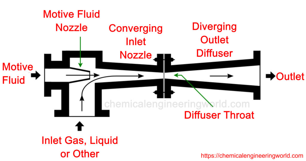
A typical single-stage ejector is made up of the following essential components:
- Nozzle
- Suction chamber
- Mixing section
- Diffuser
A high-pressure gas (also known as motive gas) is supplied through the opening of the ejector at low velocity and made to flow through a jet nozzle. As the motive gas flows through the nozzle, its pressure energy (available upstream of the nozzle) is converted into kinetic energy, resulting in low-pressure high-velocity gas exiting the jet nozzle and creating a vacuum.
This vacuum draws in the secondary fluid through the suction inlet of an outer tube . The high-velocity motive fluid from the jet nozzle entrains and mixes with this secondary fluid stream, imparting enough kinetic energy for the mixture to be ejected through the outlet of the outer tube. Keep in mind that the outer tube is gradually expanded downstream (to form a diffuser), causing the discharge pressure of the mixture to increase to up to 15 times the suction pressure.
Some key parameters in ejector design
1.Entrainment ratio
The performance of an ejector is usually described in terms of mass entrainment ratio, which can be calculated using:
Where:

Er = entrainment ratio
ms = mass flow of secondary fluid (kg/s)
mp = mass flow of the motive or primary fluid (kg/s)
The entrainment ratio describes the carrying capacity of the motive gas or simply the pumping performance of the ejector. High entrainment ratios cause shock waves to be shifted away from the mixing section, enhancing the suction of the secondary fluid stream.
2.Area ratio
Ejector structure is usually characterized by the area ratio, which is defined as the ratio between the cross-section area of the mixing section and the cross-section area of the primary nozzle throat. The area ratio also affects the efficiency of ejectors since increasing this ratio results in a corresponding increase in the entrainment ratio and reduction of backpressure.
Where:
T= area ratio
A2 = cross-section area of the mixing section (m2)
At = cross-section area of the primary nozzle throat (m2)
The area ratio can be increased by reducing the primary nozzle throat area or increasing the mixing section area, with the former being the more general practice by ejector designers. To adjust the primary nozzle throat area, many ejector manufacturers implement a moveable spindle inside the primary nozzle throat, allowing them to meet different operational requirements.
3.The velocity of the mixed fluid streams
In the thermodynamics-based analysis of most ejector designs, the motive and secondary fluid streams are assumed to be mixed at constant pressure in the mixing chamber. Also, by assuming that the two fluid streams are completely mixed at the throat of the mixing chamber, engineers can easily estimate the velocity of the mixed fluid streams using the momentum equation.

Where:
mp = mass flow of the motive fluid (kg/s)
ms = mass flow of the secondary fluid (kg/s)
V2 = velocity of the mixed fluid streams at the mixing chamber (m/s)
V1p = velocity of the motive fluid at the exit of the primary nozzle (m/s)
V1s = velocity of the secondary fluid at the suction inlet (m/s)

Engineers can also estimate the velocity of the mixed fluid streams by including the entrainment ratio parameter in the momentum equation, as shown in the equation below:
Where
Er = Entrainment ratio
One thing to note, though: there is always a loss in velocity of the mixed fluid stream. Engineers can account for this loss by including a mixing efficiency parameter, nm, which typically ranges between 85% and 95%. Hence, a better approximation of the secondary flow velocity would be:

The design process of vacuum ejectors is iterative, requiring a lot of design modifications for best performance. Engineers are advised to set some design specifications during the early design stage, for example, the flow rate, pressure and temperature values of the motive gas.
Reference
- https://en.wikipedia.org/wiki/Vacuum_ejector
- https://croll.com/vacuum-systems/applications/chemical-processing/24-2/


